I searched everywhere for a program to create the cool logo. 3D rendering software was uncommon in 1999. Most was pure garbage that crashed half the PCs to try running it. At that time a fast computer took a minute or more to render the text for this image.
There were three manufacturing fabs named after NASA programs, Apollo, Gemini and Mercury.
Apollo was a Cell Phone manufacturing fab that I designed and built. Systems like this live a short hard life and Apollo was no different. It ran constantly for over two years before the company was dismantled and sold off in pieces.
Below is the text from an old web page about the process. I wrote it, but it was a page on the parent company's website.
The Apollo Paint Line is a fully automated paint process for small plastic components. It is primarily used for painting cellular phone covers. It is a two part process involving a color coat and electrostatically sprayed top coat. Each sprayed coating is followed by the needed infrared and ultraviolet cure.
The process is entirely controlled by a Windows based software application. Each component in the system is graphically depicted in the software, status of the components is indicated by changes in the color. All aspects of the system are controlled and monitored either automatically or by use of on screen controls from the work room. The exception to this rule is control of air pressure to the individual paint guns which are controlled locally.
All machinery and back up computers are connected to an RS 485 network for control and remote monitoring of the system. Desktop computers in each of the supervisors offices are used to allow them to monitor the system. These secondary computers are capable of automatically assuming control in the event the primary PC fails to meet it's watchdog timer. Each PC on the network is given a priority assignment and is capable of assuming control of the system based on it's priority.
The control software was written in Delphi v1 to make use of 16 bit video drivers for the ATI All-In-Wonder video card. The video input allows the supervisor to monitor various points in the process, from the control software running on the primary control PC in the work room.Apollo Pictures 1999 - 2002
Some of these pictures were taken before running the first product. The rest were taken after more than two years of hard use. The difference is obvious.
On the left is the VOC abatement room (like the catalytic converter on your car). On the right is the entrance and a window to the Apollo fab.
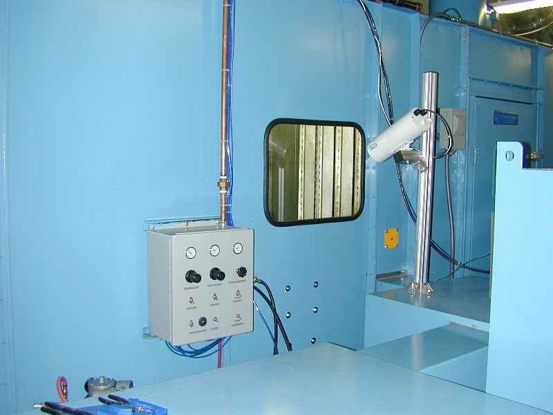
Window looking into the work room. It was a nice air conditioned pseudo clean room, using the air systems for a clean room, but it didn't need to meet all clean room requirements.
Window looking into the process room.
The work room with control computer, product loading and unloading stations plus inspection tables. My Mountain Dew and somebody's Circle K drink mug... were not allowed in the room. It was a couple years old in this pic, and it shows in damage to the wall.
Here you see the part loading station where the parts disappear through a hole in the wall. The cable and spring is an emergency stop pull cord. All those little posts sticking up got tooling attached that was made to hold specific products. Different parts each required an investment in tooling to hold the parts on the conveyor.
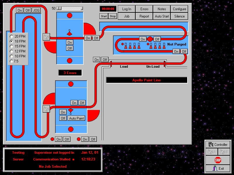
This is a screen capture of the control software I wrote. It had many functions to help with the manufacturing process and to help with maintenance of the equipment. There were cameras to monitor the spray booths. I wish I had made video files from those cameras. It kept hour meter readings on each item in the system. Supervisors had to log in to the control system, accepting responsibility. All the parameters for every job were saved and recalled to automatically set up the system when a production run was started. It data logged every single event during a production run and provided a graphical display of the data log. All the red items on the screen changed between red or green to indicate if the item was running or shut down. Even the booth doors indicated open or closed.
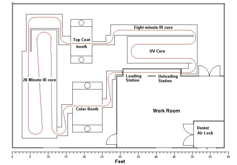
This process schematic should be self explanatory.
My network design used dependable hardware which never once failed the entire time Apollo was running. I know that because my control software would have recorded any failures. I still wanted to cover the worst case situation and wrote the software with back up capabilities. Other PC's in the maintenance office and production offices were running the control software, connected to the Apollo network and ready to take control if there had been a failure. That also allowed management to monitor the system from the offices.
The system operated under several different communications protocols that I developed specifically for this equipment. Whenever the software found itself connected to the internet, it emailed me the details of it's life. That happened only when the production manager ran the control software on his desktop computer.
This is a small amount of electrical components given the amount of equipment it controlled. That's because the actual control is done in Windows software.
Control cabinet for the 20 minute IR cure oven.
Control cabinet for the 8 minute IR cure oven.
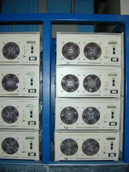
Each of the eight UV cure lamps required a giant power supply.
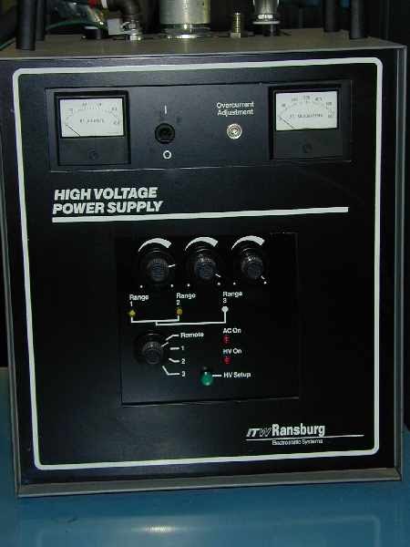
Power supply for the electro-static UV coating.
Color coat spray booth. The parts were spinning on the conveyor to allow the paint guns to hit every part of the part. Looking at the floor tells me this picture was taken after the first tests.
Pressure control for the color coat spray guns.
Looks like a real mess after a couple years use.
Ultra Violet cure zone. It was really cramped in there. I had no other option in the design. See all the antique cell phone cases? Four on each tool.
North side of the 20 minute IR oven.
Dirty view of the north side of the 20 minute IR oven, from the other perspective.
East side of the 8 minute IR oven and the side of the UV zone above.
Top of the UV cure zone. This shows some of the structure supporting the high pressure UV lamp cooling blower.
Process room wall, conveyor enclosure and color coat spray booth. It looks like a battle zone after a couple years use.
Color coat spray booth, conveyor enclosure and south side of the 20 minute IR cure oven.
Shiny new picture of the north side of the top coat booth, with the Aerobell pneumatic controls and the observation camera. Cameras were directly monitored in the control software.